


SWITCH REPLACEMENT GUIDE
This guide is for customers that need to replace their speed switch. This guide provides detailed step by step instructions to help Newport Vessels trolling motor customers with the disassembly process of the old switch and installment of the new switch. If you need additional help or get stuck on one of the steps, do not hesitate to contact us directly at (866) 721-0002.
*PLEASE READ INSTRUCTIONS THROUGHOUT BEFORE BEGINNING REPLACEMENT*
For a print friendly version click here!

1) Make sure the trolling motor throttle is set to “0” and disconnect your motor from the battery. Once the terminal ends are disconnected, the LED display will no longer illuminate.

2) Use a Phillips screwdriver to remove the six (6) screws that close the control head of the motor. These screws are located under the control head, and can easily be located visually or by feel. (3 on both sides of the control head of the motor)

3) Do not yank or pull the control box cover away! Carefully lift off the control box cover to not break the LED wiring. A thin wire links the LED lights on the top of the control head to the cables inside the motor, disconnect this by pressing on the clip located on the side and gently remove the connector. Set the cover aside. NOTE: DO NOT EXTEND HANDLE WHILE TOP COVER IS OPEN.

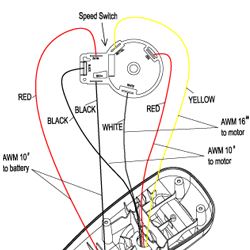
4) This is the control switch. Take several pictures of where the wires are placed inside the head of the motor. This will come in handy when reinstalling the control box cover.

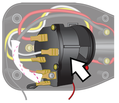
5) Remove the wires from their connections on the control switch. This can be done by gripping the base of the metal clip and firmly pulling it away from the switch. This can be done except for the 2 wires connected by screws and the black one adjacent to them on the square side of the switch.

6) To disconnect the remaining three (3) wires, remove the screw and metal tab at the bottom of the switch that secures it to the control head. Now you may move the switch by lifting the handle from its cradle to access the wires more easily.

7) The black and red wires can now be removed. Make sure to keep the screws, washers and nuts together for reassembly. The remaining black wire can now easily be pulled away from it’s contact point.

8) After the wires are removed, you can remove the switch from the control head to disconnect it from the handle. Gripping the switch in one hand and the telescopic handle shaft in the other, firmly pull the switch and handle apart. NOTE: DO NOT EXTEND HANDLE

9) Dispose of the old switch

10) To install the replacement switch, refer to the wiring photos of your motor. Connect the battery cables to the new switch, be sure they are securely fastened with the hardware. *Note - It is easier to start with the red cable and to use your fingers to begin fastening. Hold the screw still while fastening the nut, then use a screwdriver to finish tightening.

11) Reattach the switch to the handle. Be sure the flat portion of the switch lines up with the handle.

12) Next, replace the switch and control handle into the control box. Be sure to place the grooved portion into the cradle near the switch. Match the loose collar near the grip of the handle with the front edge of the plastic control case. Make sure the throttle indicator arrow is oriented to “0”. NOTE: DO NOT EXTEND HANDLE

13) Reinstall the screw and metal clip in the corresponding groove on the bottom of the switch to secure it. Make sure the wires are in their respective place so that the switch is not tilted.

14) Reattach the wires to their respective connectors on the switch. White wire connects on top, Yellow wire connects on bottom right, and the Red wire connects on bottom left. To double check, the switch has imprints of the first initial of the wire color that corresponds to the connector. Example: For the WHITE wire, a “W” is stamped under the connector.

15) After the wires are connected, double check to make sure the switch is secure, and there are no stray wires that might interfere with the fit.

16) Reconnect the LED wires, fit the control box cover and secure the six (6) screws underneath.
IMPORTANT
-
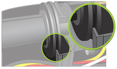
If the top cover does not fit securely, check to make sure there are no obstructions. Common areas are where the top cover and control head moldings meet.
-
Wires can also interfere with the screw housings that connect the two halves together.
-
Also, make sure that none of the wires are being pinched when reassembled.
Enjoy your new switch! Let us know if you have any questions or need help with this installation. Please give us a call at (866)721-0002 or email us at support@newportvessels.com